
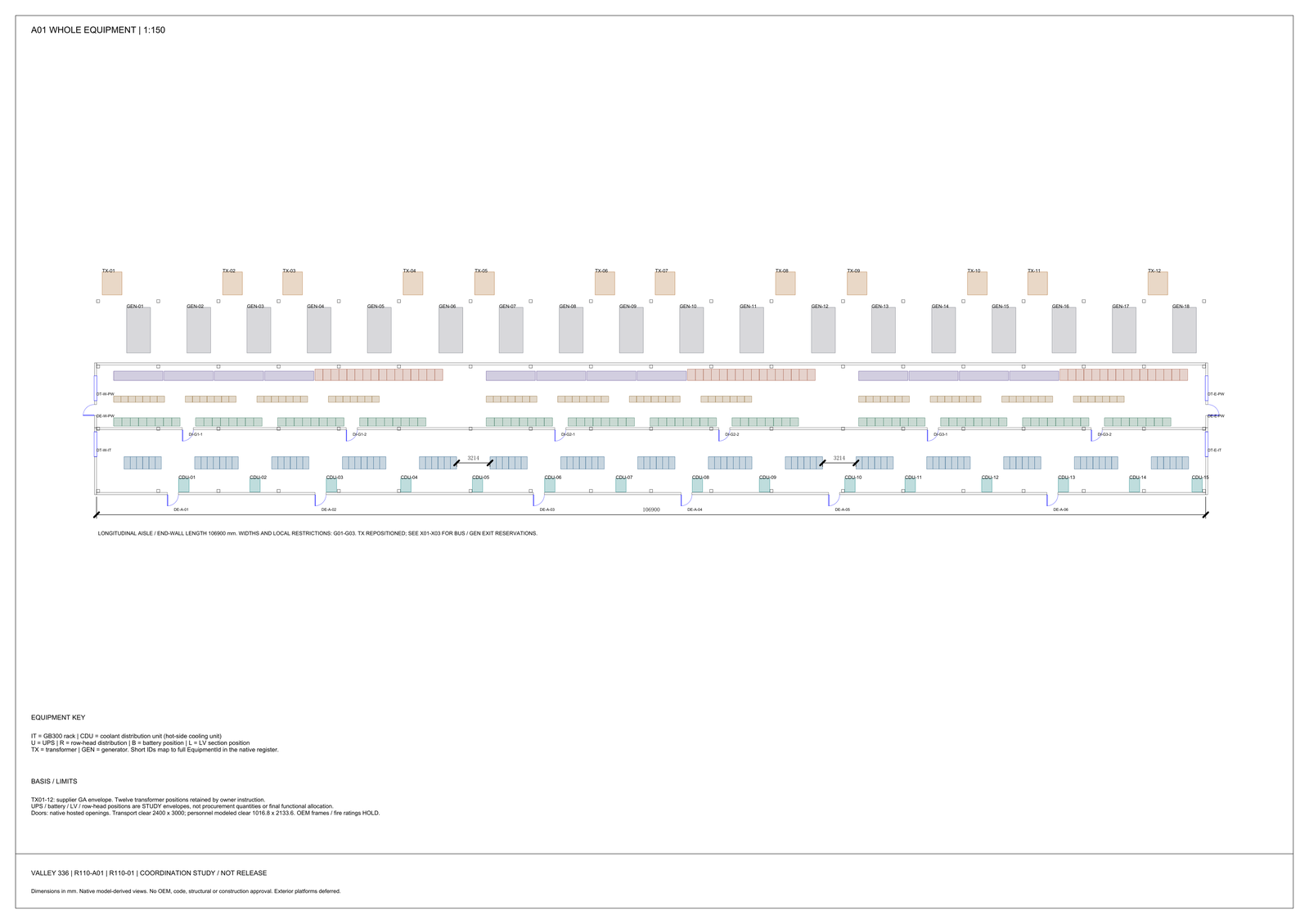
Hold every geometry symbol at its baseline and walk rack density from 100 to 140 kW per rack: whole-site white space falls from 541 to 472 m², a drop of 12.8 per cent [MODELED]. Hold density at 100 kW per rack and walk the same geometry set from its lower envelope to its upper: the area rises from 315 to 916 m², a rise of 191 per cent [MODELED]. Rack count across that ladder is 120, then 100, then 86 [MODELED]. The floor barely moves.
Cabinet count is not floor area
The first conclusion the space chapter prints is about count. Billable IT is 12,000 kW [TARGET]. Divide by each density step and the hall holds 120, 100 and 85.71 racks, the last rounded up to 86 with 40 kW of remainder and an installed 12,040 kW [MODELED]. Count falls 28.3 per cent [MODELED] from the bottom of the ladder to the top. That drop is real. It is also the wrong first-order driver for area.
The chapter then corrects itself. Cabinet count is first-order in density. Cabinet area is first-order in unit geometry and aisle clearances. At the baseline column the three steps produce 541, 507 and 472 m² [MODELED] — a twelve per cent band across a forty per cent change in rack power. Anyone who reads the count table and expects the room to shrink with it is reading the wrong table.
Column Width Contains No Density Term
Zone area is a row length times a column width. Only the row length carries a rack.
At the first density step the row is 12.65 m long and the column is 11.40 m wide, and the zone is 144.2 m² [MODELED]. That column width repeats against all three steps. It is four rows at 1.20 m deep plus two cold aisles at 1.50 m plus three hot aisles at 1.20 m: 4 × 1.20 + 2 × 1.50 + 3 × 1.20 = 11.40 [MODELED]. Nothing in that sum is a kilowatt.
The same 11.40 m later fooled a building-depth check. An earlier issue of the space chapter multiplied four zone widths and called 45.6 m a cross-check against a 46 m example depth. The revision that is now the controlled text deleted that sentence. Four times a pod width is not a building. The structural basis still writes the product as a natural modulus for column grids. The space chapter now forbids using any multiple of 11.40 m as a depth verification.
Row length moves a little. Rack pitches shrink with density. The two end clearances, the in-row cooling position and the air-side positions do not. Every pitch in that formula is an assumption. The cooling-unit pitch is a pure envelope: no supplier width, depth, height or service face exists in writing. The wider of the two ladders is the one built from the weaker evidence.
Highest Density Cannot Occupy the Narrowest Pitch
The area table is three densities against three geometry columns. Immediately beneath it the author voids one corner. A rack at 140 kW is almost certainly 800 to 1000 mm wide and 1400 mm deep with side manifolds [SENSITIVITY]. It cannot occupy the narrowest pitch column. The 274 m² that cell computes is arithmetically right and physically unreachable, and the text says it may not be quoted [SENSITIVITY].
What survives is a merged band: the 100 kW step read from lower envelope to baseline, the 140 kW step from baseline to upper. That gives 315 to 916 m² with a representative value near 500 m² [SENSITIVITY]. The three density bands overlap. The 140 kW upper envelope is 804 m² [MODELED], well above the 100 kW lower envelope of 315 m². Closing density first therefore converges nothing.
A grid of correlated variables will publish an indefensible corner unless somebody deletes it by hand.
Clear Height and the Lower Area Envelope Cannot Both Hold
The 315 m² lower envelope has a second problem, and it is not in the area table. Raise the white-space clear height far enough to take the pipe, tray and sprinkler layers. The work face then sits above 4.0 m [MODELED]. Ladders stop being a method. A mobile elevating work platform has to roll the aisle. The aisle then has to take the platform chassis, so the 1.20 m cold-aisle lower envelope does not hold in any aisle that needs the platform. The chapter's own vertical section states the lock: the 315 m² lower envelope and the upper clear-height envelope cannot both be true [FACT].
The structural basis adds a third ring to the same chain. Platform wheels are a concentrated floor case the cabinet feet do not cover. Area, floor load and height are one lock, not three independent envelopes.
Limits and open items
Confirmed: white-space area as published here is room net usable area, not building area and not site area; column width contains no density term; the 4 × 11.40 m depth product is not a building check. [FACT]
Modelled and unfrozen: 541, 507 and 472 m² at the baseline column; 315 to 916 m² across the geometry envelope; 12.65 m by 11.40 m by 144.2 m² at the first step; rack counts 120, 100 and 86; the 28.3 per cent count drop and the 12.8 per cent and 191 per cent area moves; the 12,040 kW installed remainder at 140 kW per rack. Every geometry symbol behind those figures is an assumption-graded pitch or clearance. The in-row cooling pitch is a pure envelope. None is released as a room size. [MODELED]
The 274 m² cell is a sensitivity the source computes and then strikes. The merged 315 to 916 m² band with a representative value near 500 m² is the same class. [SENSITIVITY]
Open: supplier geometry for the cooling unit and the rack; the owner's density step, which remains unselected; a licensed engineer's per-aisle ruling on working-space applicability; the fire authority's opinion on escape width and travel distance; the change candidate that would split the single registered input into a density item and a form-geometry item. Priority of work is cooling-unit geometry and rack form at or above density [TARGET]. Closing density first does not settle the floor. [HOLD]
The baseline intensity of 39 to 45 m² per megawatt [MODELED] sits on the bottom edge of an assumed industry band of 40 to 90 m² per megawatt [SENSITIVITY] for direct-liquid white space. The chapter reads that as a warning about its own inputs. It is too tight to submit as a planning area.
The floor-loading target of greater than 16 kN/m² [TARGET] shares a status no computed area in this chapter has: it is an owner requirement with no achieved value behind it. Nothing here has been reviewed or sealed by an Engineer of Record.
Which Drawing Closes Cooling-Unit Width and Rack Form
Density is still the first thing an owner is asked to decide, and it remains the input with the cleanest table behind it. That is why the gap between the two ladders is worth printing. The question worth putting to the architect is not which kilowatt step to freeze. It is which supplier drawing closes the cooling-unit width and the rack form. Until one of those arrives the area will not settle, whichever order they arrive in.
© 2026 K&K Data Service Inc. All rights reserved. Reproduction or republication is permitted only with clear attribution to K&K Data Service Inc. and a working hyperlink to the canonical URL of this article. Excerpts must preserve the technical context, maturity labels, assumptions, and limitations. No excerpt may imply project approval, field validation, certification, or endorsement that the original article does not state.
Source: K&K Data Service Inc., “White-Space Area Follows Geometry, Not kW per Rack,” https://www.kkdatasvc.com/lab/modules-and-space/white-space-area-follows-geometry-not-kw-per-rack/.
Request the Public Calculation Note. If your project record shows a different result, or the same failure domain under another name, we want to see it. Email inquiry@kkdatasvc.com or use the contact page.